Choosing the Right Velocity Sensors for Condition Monitoring
Author's note: The content in this blog was originally published by our friends at Wilcoxon Sensing Technologies.
Velocity sensors for condition monitoring are solid-state piezoelectric velocity measurement devices — essentially accelerometers with an internal integration circuit which will produce an output relative to velocity.
Acceleration, Velocity, and Displacement
Acceleration, velocity, and displacement are integrands, meaning they have a defined mathematical relationship. Velocity is the rate of change of displacement over time. Acceleration is the rate of change of velocity over time. The mathematical relationship between them can be expressed as equations. 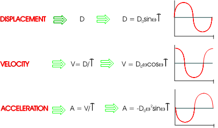
Typically, accelerometers internally generate and output voltage proportional to g's, and 100 mV/g (milli Volts per g of acceleration) is the common reference value. Piezoelectric velocity sensors, on the other hand, measure acceleration and internally integrate that measurement to velocity. The common reference value is 100 mV/ips (milli Volts per inch per second).
Noise Advantages of Piezoelectric Velocity Sensors
Many vibration analysts prefer to examine vibration signals in terms of velocity (inches per second or ips) to amplify the signal of interest. The internal integration of the accelerometer to velocity inherently eliminates distortion caused by high-frequency signals, allowing better measurement of low-frequency vibration.
Piezoelectric velocity sensors can reduce signal noise in many low-frequency measurements. The integration circuit amplifies low-frequency signals and attenuates high-frequency signals. This increases the voltage output at low frequencies and filters high-frequency noise. The increase in low-frequency voltage output reduces the noise contribution of the acquisition equipment. The inherent filtering reduces intermodulation (washover) distortion caused when high-frequency signals overload the amplifier and may reduce "ski slope" noise in some applications.
In traditional walk-around vibration systems, it is standard practice to convert the accelerometer signal to velocity after the signal reaches the measurement instrumentation. The result often seen in this data has been characterized as 'ski slope', where low-frequency signals are lost in the integration process. With a piezoelectric velocity sensor mounted on the machinery, the processing is performed right at the point of data collection. It is possible to control the entire measurement and integration process to a much greater degree and eliminate external noise that influences readings taken with handheld data collectors. With no cabling and no instrumentation before it is converted, the cleanest signal is possible, where cleanest is defined as the least amount of electrical, thermal, and cable noise before conversion.
Condition Monitoring Applications for Velocity Sensors
Velocity and acceleration sensors monitor for different faults.
Velocity is used as a vibration measurement for most condition monitoring applications because velocity is the best overall indication of machinery health for both low-speed and intermediate-speed components. Velocity measurements capture the frequency range of the most common machine faults, including imbalance, misalignment, and looseness. Velocity amplitude changes do not occur as early as acceleration but tend to increase over time for a better representation of the machine's condition.
Impact levels detected with acceleration can decrease over time even though the machine condition does not improve. Acceleration is useful for monitoring high impacts and shock, which may indicate early bearing wear or lack of lubrication in gears or bearings.
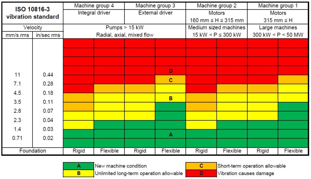
While there are no generally accepted thresholds for acceleration monitoring, standard ISO 10816 guidelines exist for velocity vibration measurements and can be used to set thresholds.
Velocity Sensors for Paper Machine Condition Monitoring
Steam seals in paper machine dryers can leak and produce very high frequency noise. This high frequency noise can overload normal accelerometers and "washover" low frequency information. The velocity sensor's attenuation of high frequency signals ensures that quality data can still be taken in areas prone to steam leaks.
Vibration Monitoring of Pumps with Velocity Sensors
Most pumps operate from 450 to 3,600 CPM (7.5 to 60 Hz) depending on site power, drive, and gearing. Most vibrations sensors are adequate for these "mid-band" frequencies. However, many destructive system faults appear at very low frequencies and are not easily detected. For instance:
- Oil whirl, oil whip, and rotor rub excite vibrations at 40 to 50% of running speed
- Hunting tooth faults on reduction gears can produce signals below 60 CPM (1 Hz)
- Destructive surge pulsations have been measured below 6 CPM (0.1 Hz)
Motion in terms of acceleration is very low at these frequencies. If low-amplitude vibrations are measured near the electronic noise floor of the sensor (or monitoring instrument), signal corruption will occur. The common "ski slope" response results from electronic noise and can obscure the low-frequency vibration information. Piezoelectric velocity sensors maximize low-frequency vibration sensitivity while retaining high-frequency capabilities, with better signal-to-noise ratio.
Pumps and piping are also susceptible to cavitation problems. The collapse of the cavitation pockets produces very high-frequency noise that can also overload an accelerometer. Velocity sensors allow effective measurement of normal vibration in the presence of severe cavitation, allowing for differentiation between the cavitation condition and typical machine vibration.
Wilcoxon's Range of Velocity Sensors
- 793V - 100 mV/in/sec sensitivity, ±10 % tolerance, 50 in/sec peak full scale range, 2.5 Hz - 7,000 Hz frequency response (±3 dB)
- 797V - Low profile, 100 mV/in/sec sensitivity, ±10 % tolerance, 50 in/sec peak full scale range, 1.6 Hz - 7,000 Hz frequency response (±3 dB)
- 793VR - Radiation-resistant (1x10⁻⁷ RADs exposure limit), 100 mV/in/sec sensitivity, ±10 % tolerance, 50 in/sec peak full scale range, 2.5 Hz - 7,000 Hz frequency response (±3 dB)
- 793V100-5 - Tight sensitivity tolerance, 100 mV/in/sec sensitivity, ±5 % tolerance, 50 in/sec peak full scale range, 2.5 Hz - 7,000 Hz frequency response (±3 dB)
- 793V-5 - High sensitivity, 500 mV/in/sec, ±10 % tolerance, 10 in/sec peak full scale range, 5 Hz - 7,000 Hz frequency response (±3 dB)
- 893V - Designed with fewer components for more reliable data,100 mV/in/sec sensitivity, ±10 % tolerance, 50 in/sec peak full scale range, 4.5 Hz - 5,000 Hz frequency response (±3 dB)
- 786V - Wide frequency range, 100 mV/in/sec sensitivity, ±5 % tolerance, 50 in/sec peak full scale range, 1 Hz - 12,000 Hz frequency response (±3 dB)
Click here to view a catalog of Wilcoxon Sensing Technologies products from Instrumart
Seismic Velocity Transducers vs. Electrodynamic Velocity Sensors
When comparing velocity sensor types, seismic velocity transducers provide superior performance in most applications when compared to older electrodynamic velocity sensors.
Piezoelectric velocity sensors:
- Utilize two-wire powering compatible with most modern data collectors, analyzers, and online vibration measurement systems
- Contain no moving parts, making them inherently more reliable than electrodynamic sensors
- Can be oriented in any direction
- Provide much lower frequency response than electrodynamic sensors. The electrodynamic sensor contains a coil that is suspended by a spring within a magnet. The natural frequency of the coil-spring assembly is typically 8 to 14 Hz (480-840 cpm) or lower. The low frequency operation of a piezoelectric velocity sensor is only limited by the capability of the sensor's integrating amplifier to provide sufficient gain as the frequency decreases.
- Reduce interference from electromagnetic fields due to the elimination of velocity coils