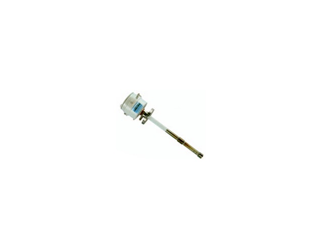
The GE Panametrics FGA311 in situ flue gas oxygen transmitter is a simple to use and low-cost.
The zirconium oxide oxygen sensor is installed directly into the flue stack or furnace wall. For
low-temperature applications, a heater is included to maintain a constant temperature on the
zirconium oxide sensor. The GE Panametrics FGA311 in situ flue gas oxygen transmitter is available
in both weatherproof and explosion-proof configurations.
Typical applications for the GE Panametrics FGA311 in situ flue gas oxygen transmitter include
natural gas-fired process heaters. The FGA311 is ideal for boiler and furnace manufacturers due
to its low-cost, basic transmitter configuration.
Easy Installation
The GE Panametrics FGA311 in situ flue gas oxygen transmitter can be supplied with standard NPT
fittings, or it can be mounted on existing process flanges, making installation quick, easy, and
inexpensive.
The electrical connections for the GE Panametrics FGA311 in situ flue gas oxygen transmitter are as
simple as 115 to 230 VAC for power and a 4- to 20-mA output signal.
Easy Configuration
Output ranges for the GE Panametrics FGA311 in situ flue gas oxygen transmitter are user-selectable
via a switch or the RS232 interface to accommodate changing measurement needs.
Easy Troubleshooting
Users can quickly connect the GE Panametrics FGA311 in situ flue gas oxygen transmitter's RS232
interface to a PC and view detailed diagnostics via terminal emulation. The FGA311's microprocessor
can report sensor mV output, heater temperature and other system status information, allowing the user
to determine quickly any necessary corrective action.
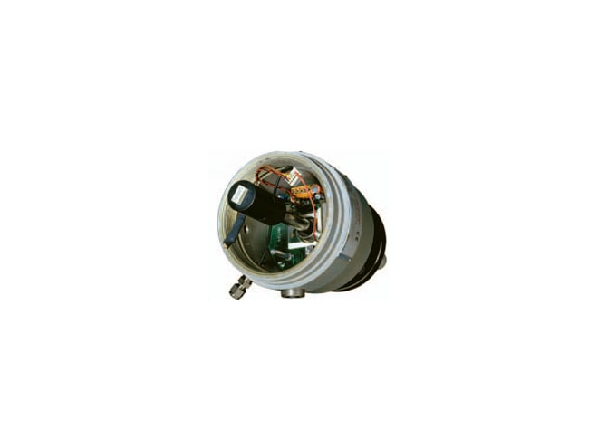
Easy Removal and Replacement of Sensor and Heater Assembly
Particulates and the corrosives of most flue gases are very harsh to instrumentation located within the
process. Conventional in situ flue gas oxygen transmitters require removal of the whole analyzer from
the sample point to replace the sensor and heater assembly. The unique design of the GE Panametrics FGA311
in situ flue gas oxygen transmitter makes the replacement easy. The cover on the transmitter housing is
unscrewed, the wire harnesses are disconnected, and the sensor and heater assembly are unscrewed and
removed. Then, simply slide the sensor and heater assembly out. The transmitter housing and probe remain
in place, reducing labor time and effort for any sensor and heater replacement needs.