Skip to Main Content
Aalborg AFM Mass Flow Meters
Thermal mass flow meter for clean gases. Replaces the AA30-C.
Overview
Features
- Rigid metallic construction
- Available flow ranges starting from 0 to 10 smL/min up to 0 to 50 sL/min
- Maximum pressure of 500 psig (34.5 bars)
- 0-5 VDC or 4-20 mA signals
- Leak integrity 1×10⁻⁹ smL/sec of helium
- Accuracy of ±1% full scale
- Totalizer option
- Circuit protection
Description
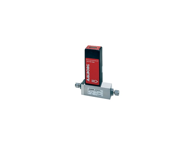
The Aalborg AFM Mass Flow Meters are designed to indicate the flow rates of gases. Each Aalborg AFM Series mass flow meter incorporates an advanced straight tube sensor in conjunction with flow passage elements constructed of stainless steel. LED readouts of command modules are supplied with 0 to 100% calibrations. Zero and span adjustments are conveniently accessible from outside of the transmitters.
The Aalborg AFM Mass Flow Meters are available with flow ranges from 10 smL/min to 100 sL/min. Gases are connected by means of 1/4", 3/8", or optional 1/8" compression fittings. Aalborg AFM Series mass flow meters may be used as benchtop units or mounted by means of screws in the base.
With input types including 0-5 VDC or 4-20 mA signals, the Aalborg AFM Series mass flow meter's transducer power supply ports are fuse and polarity protected. The Aalborg AFM Series has a leak integrity of 1×10⁻⁹ smL/sec of helium maximum to outside environment.
The Aalborg AFM Series mass flow meter offers an accuracy of &plumsn;1% of full scale, including linearity for gas temperatures ranging from 59°F to 77°F (15°C to 25°C) and pressures of 10 to 60 psia (0.7 to 4.1 bars); ±2% of full scale, including linearity ranging from 41°F to 122°F (5°C to 50°C) and pressures of 5 to 150 psia (0.35 to 10.3 bars). The Aalborg AFM Series' repeatability is ±0.2% of full scale.
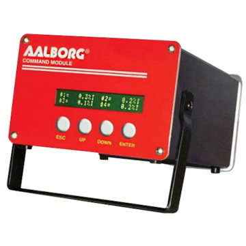
Mass Flow Systems
Complete Mass Flow Systems include Command Modules, transducers, and cables. Command modules contain appropriate power supplies, digital panel meters with 3-1/2" digit LED readouts, and high precision potentiometers. External RS-232 or RS-485 are optional. Analog outputs are accessible through convenient 9 pin D-connectors.
Principles of Operation
Metered gases are divided into two laminar flow paths, one through the primary flow conduit and the other through a capillary sensor tube. Both flow conduits are designed to ensure laminar flows; therefore, the ratio of their flow rates is constant.
Two precision temperature sensing windings on the sensor tube are heated, and when flow takes place, gas carries heat from the upstream windings to the downstream windings. The resultant temperature differential is proportional to the change in resistance of the sensor windings.
A Wheatstone bridge design is used to monitor the temperature dependent resistance gradient on the sensor windings which is linearly proportional to the instantaneous rate of flow. Output signals of 0 to 5 VDC or 4 to 20mA are generated, indicating mass molecular based flow rates of the metered gas.
Flow rates are unaffected by temperature and pressure variations within stated limitations.
Documents
Need Help? Call a Flow engineer at 1-800-884-4967
We're open Mo-Th 8am to 5:30pm. Fr 8am to 5pm ET